


Business Solutions
How Fiber Optic Receivers Enhance RF Conversions

Looking forward, integrated photonics may allow an entire conversion chain to fit onto a single chip. Such a design could drastically reduce power consumption and form factor while boosting performance. Fiber optic receivers, in tandem with these specialized chips, might soon handle multiple frequency bands concurrently, switching dynamically based on network load or environmental conditions. This adaptability could pave the way for agile, reconfigurable networks that seamlessly scale to match global data traffic demands.
Organizations that keep an eye on these developments stand to gain a competitive edge, whether in telecom, defense, or broadcast. By staying current with the latest converter rf breakthroughs and the next generation of fiber optic receivers, businesses can future-proof their infrastructure against rising bandwidth requirements and the relentless march of innovation. The synergy between these technologies looks set to continue reshaping communications, offering a blueprint for systems that are more efficient, secure, and capable than ever.
Introduction to Converter RF and Fiber Optic Receivers
Converter rf equipment often forms the backbone of systems requiring reliable frequency translation. In such setups, signals may need to be converted (up or down) to facilitate specific tasks. Meanwhile, fiber optic receivers tackle the challenging realm of transporting these signals across long distances with minimal attenuation. One of the biggest reasons these technologies fit well together is their capacity to handle higher frequencies in a cleaner, more secure way than older, coax-based solutions. When signals move from the radio frequency domain into the optical domain, they can traverse extensive networks without succumbing to common pitfalls like electromagnetic interference.
Organizations spanning telecommunications, aerospace, and research labs benefit from combining converter rf and fiber optic receivers. The synergy between these devices allows them to push data faster and farther, all while retaining quality. Over time, as systems scale up or adapt to new standards, integrating new frequencies becomes simpler. This approach has proven invaluable in everything from satellite communications to advanced sensor applications, where clarity and fidelity are paramount.
Understanding RF Conversion Fundamentals
Radio frequency conversion plays a critical role in modern communication designs. At its simplest level, an RF signal can be shifted upward (upconversion) or downward (downconversion) to match the requirements of a particular system. By altering the frequency range, these signals become more manageable, either because they avoid interference in specific bands or because certain hardware performs more effectively at certain frequencies. While it seems straightforward, the underlying technology is quite intricate, relying on mixers, local oscillators, amplifiers, and filters to ensure the final signal remains clean and stable.
Two paragraphs might not suffice to unravel every element of frequency conversion, but they highlight the complexity and importance of these steps. Whether dealing with microwave links or satellite feeds, the converter rf stage must handle even the slightest changes in amplitude or phase. If not carefully managed, distortion creeps into the system, causing data loss or degraded communication. This is one reason hardware selection and design criteria demand precision. Shoddy mixers or poorly implemented oscillators often lead to cascading issues downstream.
The Core Role of Fiber Optic Receivers
Fiber optic receivers bridge the gap between optical signals and the electrical domain. Unlike copper cables, optical fibers are immune to electromagnetic interference, allowing them to maintain signal integrity over significant distances. As frequency demands intensify—particularly when systems rely on converter rf stages to move signals around the spectrum—fiber comes to the rescue by preserving each bit of information as pulses of light. Traditional copper solutions can’t offer the same low-loss, high-bandwidth advantages, especially over many kilometers.
One reason these receivers excel is their sensitive photodiodes that convert incoming light back into an electrical current. With proper calibration, they can detect minuscule variations in optical intensity, ensuring the original RF data remains faithful to its source. As high-frequency deployments grow more prevalent in defense, broadcasting, and scientific research, fiber optic receivers become vital. They align perfectly with upconverted or downconverted signals, mitigating problems like crosstalk or signal degradation. In essence, they’re the missing puzzle piece that ensures data transitions smoothly from light to radio frequency and back again.
Minimizing Noise and Distortion
Keeping noise and distortion at bay is paramount for any RF-based setup. When signals undergo conversion, they risk unwanted interference introduced by mixing processes, local oscillator leakage, or suboptimal filtering. This contamination can worsen if the system relies on copper-based transmission lines for intermediate stages, as electromagnetic fields or thermal noise may further degrade signal integrity. The combined effect is often observed as a lowered signal-to-noise ratio, making it harder to decode or transmit data reliably.
Engineers tackle these hurdles in a variety of ways. They might shield sensitive circuitry or incorporate advanced filtering that hones in on the desired frequency band. Sufficient gain control also matters; too much amplification might saturate the mixer and add nonlinear distortion. Meanwhile, too little amplification can render the signal too weak once it hits the next stage. Incorporating fiber optic receivers adds another layer of protection. Because optical media does not conduct electricity, it eliminates pathways for external noise. Signal clarity remains high, even in environments rich in high-power electronics or radio emissions.
One of the lesser-discussed elements is temperature stability. Components like mixers and oscillators can drift slightly in frequency with changes in ambient conditions. Over time, small drifts accumulate and shift the signal away from its target band. Engineers often add temperature-compensating circuits or place converters in controlled enclosures to preserve alignment. By adopting such strategies, they ensure the system stays firmly locked on the desired channel, minimizing distortion from environmental factors.
Designing a Reliable Converter RF Setup
Crafting a robust architecture around converter rf starts with identifying clear goals: required frequency range, power levels, and data throughput. Once those are set, designers look at link budgets, choosing appropriate amplifiers and filters to ensure minimal loss. It helps to think of the signal path as a chain where each link must be as strong as the next. A single weak or mismatched component can drag down overall performance, causing errors that ripple through the entire communication system.
Many designers also incorporate fallback or redundancy. For mission-critical applications—like emergency communication networks—having multiple converter rf paths ensures that the system stays operational even if one line fails. This approach might involve parallel modules running slightly different frequencies or backup fiber routes that circumvent the primary link. The aim is always to avoid single points of failure. Additionally, adopting fiber optic receivers acts as a protective measure. Their inherent immunity to electromagnetic interference and ability to handle high data rates with low attenuation improves the reliability of each link in the chain.
Comparing Analog vs. Digital RF Conversion
When moving signals into different frequency bands, you can choose analog or digital methods. Analog conversion preserves the waveform’s continuous nature, which can be valuable when ultra-low latency or high fidelity is the priority. However, it may be more susceptible to noise and may need precisely matched mixers, filters, and oscillators to deliver consistent results. In contrast, digital conversion processes the waveform as bits, potentially enabling sophisticated error correction and compression. But digital systems may introduce additional latency and can demand higher power or more complex equipment.
Neither approach is universally better. The choice boils down to application requirements. Satellite operators or radio astronomers might lean toward analog to capture subtle signal variations. Streaming platforms or data centers handling massive volumes might opt for digital to leverage advanced encoding or encryption. In both cases, fiber optic receivers support the final stages, transmitting the signal—be it analog or digital—across optical fibers with minimal loss. That synergy points to why converter rf solutions must be carefully matched to the overall design, factoring in cost, performance, and future scalability.
Many engineers find themselves in hybrid scenarios. Certain parts of a system run analog conversions, while others incorporate digital front-ends to handle tasks like filtering or signal conditioning. While it can add complexity, a hybrid design can maximize performance in specific regions of the signal path. Ultimately, both analog and digital revolve around the same objective: deliver the highest-quality data from point A to point B with minimal noise or distortion.
Selecting the Right Fiber Optic Receivers
Choosing suitable fiber optic receivers involves evaluating criteria like sensitivity, dynamic range, and operational wavelength. Sensitivity indicates how weak a signal the receiver can interpret accurately, which becomes critical when spanning large distances or working at higher frequencies. Dynamic range reveals how well the receiver handles both faint and strong signals without distorting either one. Additionally, different fibers use distinct wavelength windows—commonly 1310 nm or 1550 nm—so matching the receiver’s wavelength capabilities to the system is essential.
Environmental conditions also play a part. Receivers must handle temperature variations, humidity, and, in some cases, vibrations from heavy machinery. Industrial or ruggedized models include sealed enclosures and reinforced connectors to cope with extreme settings. Meanwhile, in controlled environments like data centers, simpler enclosures might suffice, focusing more on raw performance metrics. Investing in high-quality receivers can yield dividends later, as subpar components often introduce incremental losses or require frequent maintenance.
Cost is another consideration. Fiber optic receivers span a wide range of price points based on their complexity and intended frequency range. Cheaper units might work well for short distances or simpler topologies, but advanced converter rf setups often justify premium hardware to ensure consistent, reliable transmission. Adopting a forward-looking strategy, where a slightly more capable receiver can handle upcoming expansions, prevents frequent hardware swaps down the road.
Handling High-Frequency Signal Loss
Operating at higher radio frequencies tends to amplify the impact of signal loss. Resistive losses, dielectric absorption, and scattering effects all become more pronounced. As frequencies climb, coax lines can quickly diminish signal power unless accompanied by repeaters or high-gain amplifiers. It’s here that combining converter rf with fiber optic receivers presents a compelling solution. By converting signals into optical form, one can largely circumvent the crippling losses inherent in copper lines at high frequencies.
In some sectors, like 5G infrastructure or military communication, signals in the millimeter-wave region (above tens of GHz) face extreme attenuation. Even short runs can cause noticeable degradation. A robust converter stage followed by fiber transmission can reduce or eliminate such problems. Additionally, splicing modern low-loss fiber cables has become fairly routine, making it simpler to extend or modify networks without incurring heavy signal penalties.
Engineers must also watch for mechanical factors. Kinks or bends in the fiber can lead to partial reflections of the light beam, lessening the net power at the receiver. Carefully planned cable trays and protection against crushing forces ensure the optical path remains consistent. While fiber is somewhat fragile, it repays careful handling with stable, long-term performance superior to nearly any coax alternative in high-frequency contexts.
Integrating Converter RF with Existing Systems
Merging advanced converter rf equipment into current infrastructure can be tricky. Legacy systems might rely on outdated interfaces, or they could be locked into certain frequencies. Determining how best to align new modules requires careful planning. You might need adapters or specialized couplers to bridge older coaxial ports with fresh optical lines. Another factor is the power supply, especially if older racks can’t deliver the voltage or current needed for advanced converter units.
Some operators address these challenges by phasing in new hardware. They partition sections of the network, upgrading them incrementally. This approach reduces downtime while still maintaining partial functionality. Over time, the entire system transitions away from older technology and reaps the benefits of fiber optic receivers and modern conversion methods.
Documentation becomes critical. Clear wiring diagrams, frequency allocations, and device configurations help troubleshoot any issues that arise after integration. Large facilities often keep a thorough inventory of components, so technicians can identify or replace any part if something goes awry. By incorporating modern converter rf modules gradually, organizations minimize risk while progressively elevating system performance.
Testing and Calibrating RF Networks
Regular testing and calibration ensure your converter rf network operates as intended. Technicians typically measure power levels, frequency accuracy, noise figures, and other performance metrics. Spectral analyzers may highlight unwanted spurious signals, local oscillator leakage, or mixing products. Identifying these anomalies early can prevent disruptions or wasted bandwidth. Some setups also rely on reference signals to keep local oscillators locked to a precise standard, ensuring minimal drift over time.
Calibrating fiber optic receivers is equally crucial. Even small variations in a photodiode’s gain can lead to discrepancies in output power, complicating data processing. Organizations often schedule calibration intervals, especially where continuous operation is a must, such as in broadcasting or defense communications. With advanced digital monitoring, systems can send alerts if performance dips below a set threshold, prompting preventive maintenance before an outright failure occurs.
Beyond the hardware, software alignment matters. Configurations for modulation schemes, error correction, and bandwidth settings must harmonize between transmitters and receivers. If parameters become mismatched—perhaps during a firmware update—communication can degrade rapidly. Testing is the final safeguard that ensures these elements align, supporting consistent, high-quality links.
Maintenance Tips for Long-Term Performance
Prolonged uptime hinges on adopting preventive measures. For instance, fiber connections benefit from routine cleaning of connectors to remove dust or small particles that might scatter light. Periodic re-checking alignment angles can keep signals optimized. Because converter rf modules include sensitive mixers and oscillators, verifying temperature control mechanisms should also be part of regular maintenance schedules.
Many professionals log performance metrics over time to detect trends that suggest hardware fatigue or environmental influences. If a power amplifier consistently overheats in summer months, it might point to ventilation issues in the equipment rack. Similarly, fluctuations in local oscillator stability could trace back to a failing internal voltage regulator. Addressing these insights proactively mitigates system-wide breakdowns.
In some high-availability networks, remote monitoring software plays a key role. Automated alerts draw attention to anomalies—like sudden drops in optical power or shifts in local oscillator frequency. These timely notifications let engineers intervene early. Ultimately, a blend of hardware upkeep, environmental management, and real-time analytics ensures converter rf and fiber optic receivers remain in prime working condition.

Business Solutions
Optical Delay Lines: The Precision Solution Reshaping Radar and Altimeter Testing
Summary: Radar and altimeter systems must be rigorously tested and calibrated before deploymen-but transmitting live RF energy to simulate target returns is impractical, hazardous, and often impossible in a laboratory or depot environment. This article explains how optical delay lines (ODLs) solve this fundamental challenge, how they work, why fiber-based delay lines outperform electronic alternatives, and how RFOptic’s specialized ODL solutions support radar and altimeter testing programs across defense and aviation markets.
Radar and altimeter testing is one of the most technically demanding areas in defense electronics validation. Systems must be verified to perform accurately across a range of simulated target distances, velocities, and environments-yet doing so by physically placing reflecting targets at the required distances is seldom feasible. The solution lies in optical delay lines, a technology that uses the fixed propagation speed of light in optical fiber to introduce precisely controlled time delays into an RF signal, simulating the time-of-flight of a radar return at a specified range.
The Testing Problem: Why You Cannot Simply Transmit to a Real Target
A radar system determines the range of a target by measuring the round-trip time of a transmitted pulse. An altimeter determines altitude by measuring the time for the transmitted signal to reflect off the ground and return. In both cases, the fundamental measurement is time-of-flight -and testing this measurement requires introducing a known, accurate delay between the transmitted signal and the simulated return.
In field testing, this can be done by physically placing a reference reflector at a known distance. But field testing is expensive, weather-dependent, logistically complex, and often impossible for airborne altimeters (which would require flight testing to validate each range point) or for classified radar systems that cannot be operated in environments where frequency emissions are monitored or regulated. Depot-level maintenance and factory acceptance testing require a bench solution.
Electronic delay lines-switched networks of lumped inductors and capacitors, or surface acoustic wave (SAW) devices-have historically been used for this purpose. But they carry significant limitations: limited frequency range, high insertion loss, temperature-dependent performance, and the inability to cover the multi-microsecond delays needed to simulate distant targets without cascading multiple stages and accumulating noise and distortion.
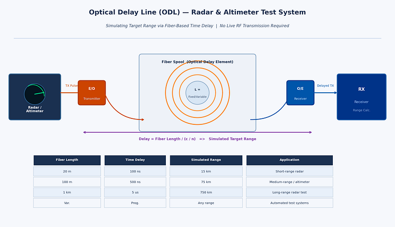
How an Optical Delay Line Works
An optical delay line converts the RF signal to be delayed into an optical signal using an electro-optic modulator or laser diode, routes that optical signal through a calibrated length of single-mode optical fiber, then reconverts it back to an RF signal at the output using a photodetector. Since light travels through fiber at approximately 2×1⁰⁸ meters per second (about two-thirds of the speed of light in vacuum), a specific fiber length produces a very precise and stable delay.
For example, approximately 100 meters of fiber produces a delay of around 500 nanoseconds-equivalent to a radar range of approximately 75 kilometers in a monostatic radar configuration. Variable delay lengths can be achieved through switched fiber spools, allowing test equipment to simulate targets at multiple programmable ranges without moving any physical hardware.
The key performance advantages of fiber-based delay lines compared to electronic alternatives are:
• Extremely low loss: optical fiber introduces negligible signal loss per unit length compared to coaxial cable or electronic delay elements at microwave frequencies.
• Frequency independence: the delay is determined purely by the fiber length, not the frequency of the signal. The same ODL works equally well at 1 GHz and at 40 GHz, making it suitable for multi-band radar and wideband altimeter testing.
• Excellent phase stability: fiber delay is not affected by electromagnetic interference and shows very low thermal drift compared to electronic delay networks.
• Scalability: very long delays (microseconds to tens of microseconds) equivalent to hundreds or thousands of kilometers of range-are achievable simply by using more fiber, without cascading lossy electronic stages.
• Electrical isolation: optical fiber passes no DC current and provides complete galvanic isolation between the input and output RF ports, eliminating common-ground interference paths in complex test setups.
Variable and Programmable Optical Delay Lines
The most operationally useful ODL systems offer variable or programmable delay-the ability to switch between multiple discrete delay values to simulate different target ranges. This is achieved through optical switching networks that connect the RF signal to different fiber spools of different lengths, or through continuous variable delay mechanisms using motorized fiber stretchers or optical path length adjustment.
Programmable delay lines are essential for acceptance testing of radar systems that must perform across the full specified range envelope. Rather than resetting physical hardware for each range point, the test engineer selects the desired delay from the ODL’s control interface, and the system switches to the appropriate fiber path within milliseconds. For automated production test environments, this enables rapid, software-controlled multi-point range calibration.
According to the IEEE Transactions on Microwave Theory and Techniques, optical delay line technology has advanced considerably with the integration of programmable switching and temperature compensation, making modern ODL systems suitable for demanding calibration environments where measurement uncertainty must be minimized.
Altimeter Testing: A Specialized Requirement
Radio altimeters-used in commercial aviation, military aircraft, and UAVs to measure height above terrain-are safety-critical systems with stringent testing requirements. Regulatory bodies including the FAA and EASA require verification of altimeter accuracy across the full operating altitude range, typically from near-zero to several thousand feet. Testing each altitude point requires introducing the corresponding time delay between the transmitted altimeter signal and the simulated ground return.
Modern radar altimeters typically operate in the 4.2–4.4 GHz frequency band, though next-generation systems and those for unmanned platforms span wider ranges. Key testing parameters include:
• Absolute accuracy: the altimeter must measure altitude to within a defined tolerance across the full range.
• Response time: the altimeter must update its reading within a specified latency when altitude changes rapidly-important for terrain-following and automatic landing systems.
• Interference immunity: with 5G networks now deployed in the 3.7–4.2 GHz C-band in many countries, regulatory concerns about altimeter interference have made test coverage of adjacent-band interference scenarios a new requirement.
An optical delay line test system for altimeter applications must cover the altimeter’s full altitude range (typically equivalent to delays from a few to several hundred nanoseconds), handle the altimeter’s specific frequency band, and provide calibrated, repeatable delay values. For aircraft integration testing, the system must also operate reliably in the electromagnetic environment of an avionics test bench.
RFOptic’s Optical Delay Line Solutions
RFOptic offers customized low and high frequency optical delay line solutions for testing and calibrating radar and altimeter systems. The company’s ODL product line is described as one of its core competencies, offering both standard and application-specific configurations.
RFOptic provides both fixed and programmable delay configurations, with the following key characteristics as described on their platform:
• Coverage from low frequency through high-frequency microwave and mmWave bands, supporting both current-generation radar and altimeter systems and next-generation wideband applications.
• Customized ODL systems developed to customer specifications, including integration with specific test equipment interfaces and control software.
• Online request-for-quote tool for customized ODL and altimeter ODL systems, supporting design consultation from the earliest project stage.
• Subsystem integration: RFOptic’s ODLs can be integrated into complete radar and altimeter test subsystems, combining the delay function with signal conditioning, switching, and management interfaces.
RFOptic’s value proposition emphasizes that in the pre-sales stage, the company builds solutions tailored to customer needs, including simulations that predict link behavior-particularly important for ODL systems where target delay accuracy and dynamic range must be verified analytically before hardware is built.
Emerging Applications: UAV Altimeters and Radar Testing
The rapid growth of unmanned aerial systems (UAS/UAV) has created a new generation of altimeter testing requirements. Drone altimeters are smaller, lighter, and often operate in different frequency bands than traditional aviation altimeters. They must be validated for low-altitude terrain-following, precision landing approaches, and operation in spectrum-contested environments. The same fundamental principle applies: fiber-based optical delay lines provide the most accurate and flexible platform for simulating the required altitude ranges in a laboratory setting.
For those evaluating radar testing solutions, the combination of programmable delay ranges, wide frequency coverage, and low noise floor that optical delay lines provide makes them the reference tool of choice across military radar, commercial aviation, and UAV development programs.
Conclusion
Optical delay lines represent a technically elegant solution to one of the oldest problems in radar and altimeter development: how to test time-of-flight accuracy without deploying hardware into the field. By leveraging the fixed and stable propagation speed of light in optical fiber, ODL systems deliver highly accurate, repeatable, and frequency-independent delay values that electronic alternatives cannot match at microwave and mmWave frequencies.
For radar system developers, avionics test labs, and depot maintenance facilities, investing in optical delay line test equipment-particularly programmable systems capable of simulating multiple range points-is a practical step that reduces test time, improves calibration accuracy, and future-proofs the test infrastructure for next-generation wideband radar and altimeter systems.
Summary: As 5G networks push into the millimeter-wave (mmWave) frequency bands, the challenge of accurately testing these systems in a laboratory environment has grown dramatically. This article examines the unique testing demands of 5G FR2 mmWave devices, why traditional coaxial test setups struggle at these frequencies, and how RF over fiber technology enables more accurate, repeatable, and scalable 5G test environments. It also outlines how RFOptic’s purpose-built RFoF solutions address the needs of 5G/6G testing engineers worldwide.
The global rollout of 5G networks represents one of the most complex RF engineering challenges in telecommunications history. For the test and measurement community, it has introduced equally demanding new requirements – particularly as deployments move into the mmWave spectrum. Engineers evaluating whether their test infrastructure is ready should start with a foundational question: can your signal transport method keep up with the frequencies you are testing? Exploring rf over fiber technology is increasingly the answer that test labs are arriving at.
Understanding 5G FR2: The mmWave Challenge
5G is defined by two frequency ranges. FR1 covers the sub-7 GHz bands familiar from 4G LTE, while FR2 – often called mmWave 5G – covers bands from approximately 24.25 GHz up to 52.6 GHz in the current 3GPP standard framework, with future extensions anticipated beyond 100 GHz for 6G precursor research. These FR2 bands offer multi-gigahertz of contiguous spectrum, enabling peak data rates measured in gigabits per second and ultra-low latency performance that FR1 alone cannot deliver.
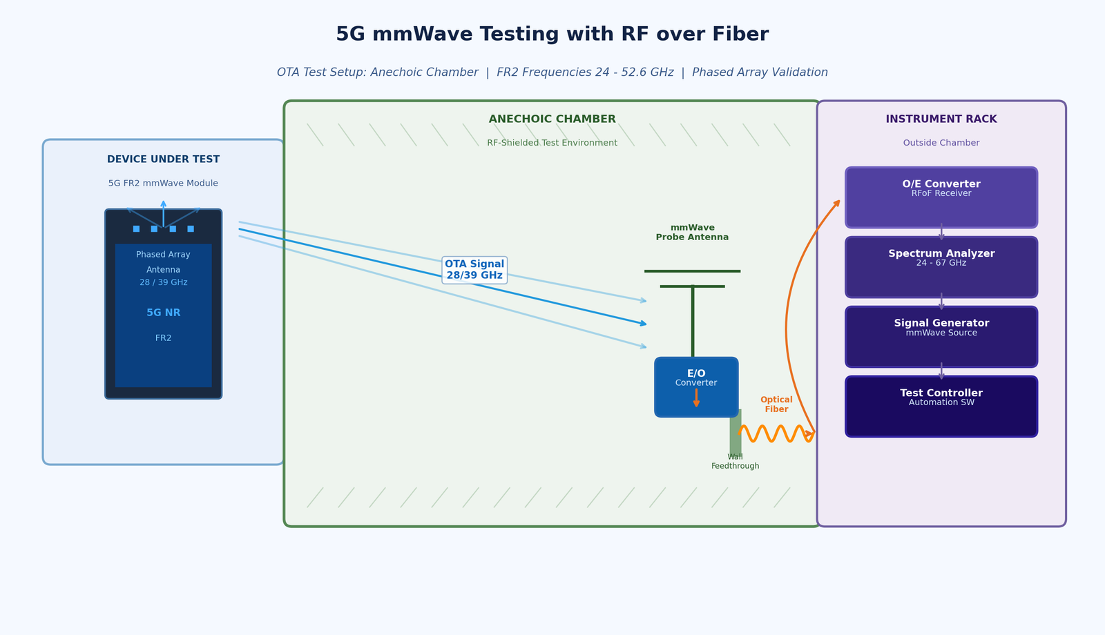
However, mmWave signals propagate very differently from sub-6 GHz RF. They are attenuated much more rapidly in air, blocked by building materials, and absorbed by the body of a device under test. This means 5G mmWave devices almost universally rely on beamformed, phased array antenna systems – integrated directly into the device – that electronically steer a narrow beam to maintain link quality.
For test engineers, this creates a significant problem: these integrated antenna arrays cannot be physically connected to a test instrument via a coaxial cable. Testing must be done over the air (OTA) – meaning the device radiates its signal in free space, and test instruments must receive and analyze the radiated field. This in turn demands anechoic or semi-anechoic chamber environments, precise positioning, and signal transport from the antenna probe in the chamber to the instrument rack outside it.
The 3GPP’s technical specifications for 5G OTA testing are detailed in the TS 38.521 and TR 38.810 documents, which outline measurement configurations for FR2 devices. 3GPP Technical Specifications provide the industry baseline against which all 5G OTA test methodologies are validated.
Why Coaxial Cable Fails the 5G FR2 Test
At sub-6 GHz frequencies, the losses introduced by a coaxial cable between a test antenna and an instrument are manageable. At 28 GHz or 39 GHz, they are not. Signal attenuation in standard coaxial cables at mmWave frequencies is dramatically higher – often 2 to 4 dB per meter or more at Ka-band frequencies, depending on cable diameter. For a test setup with antenna probes positioned several meters from the instrument, this means severe signal degradation.
The consequences are measurable and serious:
- Higher noise floor in the measurement system, reducing sensitivity and making it harder to detect weak signals from the device under test.
- Reduced dynamic range, preventing the system from characterizing both strong and weak signals in the same measurement sweep.
- Phase instability due to coax mechanical sensitivity — even bending a cable can shift its phase response, introducing errors in phase-sensitive measurements like EVM (Error Vector Magnitude).
- Impractical cable management: at mmWave frequencies, even small connectors introduce insertion losses and mechanical fragility becomes a reliability concern in frequently reconfigured test environments.
- Fundamental frequency limits of most coaxial assemblies make coverage above 40 GHz an engineering challenge requiring specialized and expensive waveguide solutions.
RF over Fiber as the 5G Test Infrastructure Standard
RF over fiber addresses the signal transport problem in 5G FR2 test environments at the fundamental level. Instead of routing the mmWave signal through coaxial cable, RFoF converts it to an optical signal immediately at the antenna probe and transports it over optical fiber to the instrument. Optical fiber has negligible attenuation in the relevant transmission windows (on the order of 0.3 dB/km), is completely immune to electromagnetic interference, and does not introduce phase errors due to bending or temperature changes.
For 5G test labs, this translates to practical advantages:
- Probe-to-instrument distances of tens of meters or more with minimal signal degradation – enabling large anechoic chambers and flexible test geometries.
- Consistent signal integrity that enables accurate, repeatable measurements across multiple test runs and different environmental conditions.
- Freedom from EMI: test chambers often house high-power amplifiers, switching equipment, and other RF sources. Fiber is immune to all of this.
- Simplified test cell design: replacing bundles of mmWave coaxial assemblies with a single fiber link dramatically reduces installation complexity.
RFOptic’s Role in 5G/6G Testing
RFOptic’s stated mission is to provide state-of-the-art RF-optical solutions with superior performance to the 5G/6G testing emerging markets. The company describes itself as a solutions provider and R&D-driven innovative manufacturing company with global coverage and extensive experience with customized solutions for the 5G testing markets.
RFOptic offers what it describes as top-notch RF-over-glass commercial off-the-shelf products for civil 5G and defense applications. Key elements of their 5G testing product line include:
- Off-the-shelf RF over fiber links covering from DC to 67 GHz in three family groups, providing frequency coverage from well below FR1 through the complete FR2 band and into mmWave territory relevant for 6G research.
- HSFDR (High SFDR) links optimized for applications where spurious-free dynamic range and signal stability are paramount – exactly the conditions required for accurate 5G OTA measurements.
- Subsystems and end-to-end solutions per customer requirements, recognizing that 5G test labs often have specific chamber dimensions, device categories, and measurement configurations that require tailored signal transport architectures.
- Remote management: all links and subsystems are managed by local or remote management interface, supporting the integration of RFoF links into automated test system software environments.
RFOptic also provides an online RFoF link calculator tool to assist test engineers in predicting link performance parameters including noise figure, gain, and dynamic range for their specific configurations – enabling accurate test system planning before hardware deployment.
Anechoic Chambers and Remote Antenna Applications
One of the most direct 5G test applications for RFoF is the anechoic chamber setup. In this configuration, the test antenna (probe) is inside the shielded chamber, while the signal generator and analyzer are in the equipment rack outside. Connecting these requires passing the mmWave signal through the chamber wall – a location where coaxial feedthroughs introduce insertion loss, potential leakage, and EMI ingress.
RFOptic offers specific solutions for anechoic chamber applications, recognizing that this is a core use case in the 5G test environment. The optical fiber feedthrough eliminates the shield integrity problem and allows the full mmWave bandwidth to be transported without the frequency-dependent losses of coaxial alternatives.
Preparing for 6G: The Frequency Frontier
While 5G mmWave deployments are still in early phases in many markets, research and pre-standardization work on 6G has already begun at frequencies above 100 GHz – the D-band (110–170 GHz) and beyond. Test infrastructure being deployed today for 5G FR2 will increasingly need to serve as the foundation for 6G research environments.
Choosing RFoF solutions with frequency coverage well beyond the immediate 5G FR2 requirement provides a degree of future-proofing for test facilities. RFOptic’s product family, which extends to 67 GHz in its standard off-the-shelf range, positions test labs to expand measurement capability as 6G frequencies become relevant for device and system characterization.
Engineers specifying rf over fiber modules for 5G test infrastructure are therefore making a technology investment with a long useful life – particularly when the solution comes from a vendor with demonstrated capability well above the minimum required frequency and with a track record of supporting customized configurations.
Conclusion
The shift to 5G FR2 mmWave testing has fundamentally changed what test and measurement infrastructure must deliver. Signal transport between antennas and instruments across the 24–40 GHz range demands low loss, phase stability, EMI immunity, and scalability that coaxial cable cannot reliably provide. RF over fiber has become the standard solution for forward-thinking 5G test labs, and its role will only grow as the industry progresses toward 6G research frequencies.
For test engineers and lab managers evaluating their signal transport architecture, the key criteria are frequency coverage, dynamic range, phase consistency, and the availability of system-level support. Purpose-built RFoF solutions from experienced high-frequency vendors offer the complete package for today’s 5G test challenges and tomorrow’s 6G requirements.
Business Solutions
RPA Security Citizen Developer Governance: The Automation Risk Nobody Is Talking About
Summary: Robotic Process Automation (RPA) has become a cornerstone of enterprise digital transformation, enabling organizations to automate repetitive tasks at scale and free human workers for higher-value activities. But the widespread deployment of RPA bots – increasingly built by non-technical citizen developers rather than professional developers – has created a largely invisible security risk. From over-privileged bot credentials to unmonitored data flows and abandoned automations, the RPA attack surface is growing faster than most security programs can track. This article explores the key security risks in enterprise RPA environments, how citizen developer governance is evolving, and how purpose-built platforms are closing the gap.
The RPA Revolution and Its Security Shadow
Robotic Process Automation – the use of software bots to mimic human interactions with applications and automate repetitive business processes – has become one of the defining technologies of enterprise digital transformation over the past decade. From processing invoices and onboarding employees to reconciling financial data and managing IT service tickets, RPA bots now operate at the heart of critical business processes across virtually every industry.
The market for RPA has grown dramatically, with platforms like UiPath, Automation Anywhere, and Blue Prism embedding themselves deeply into enterprise technology stacks. More recently, low-code RPA capabilities have been integrated directly into broader no-code platforms, with Microsoft’s Power Automate and Salesforce’s Flow Builder enabling any business user to create automated workflows without dedicated RPA tools or expertise.
This democratization of automation has delivered genuine value. Organizations have eliminated backlogs, reduced error rates, accelerated processing times, and redeployed human talent to work that requires judgment and creativity. But the same forces that have made RPA so powerful have also created a security problem that most enterprises have been slow to recognize and even slower to address.
Why RPA Creates a Distinct Security Risk Profile
RPA bots occupy an unusual position in the enterprise security landscape. They are software – and therefore subject to all the vulnerability risks of any enterprise application. But they are also trusted actors within enterprise systems: they log in to applications, access databases, execute transactions, and handle sensitive data with credentials that are often highly privileged.
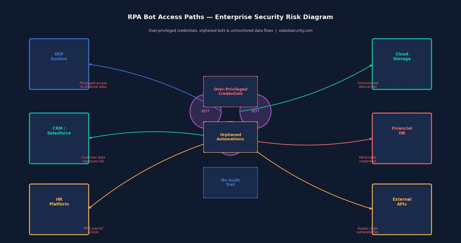
This combination – software with the access rights of a trusted human user – creates a security risk profile that is distinct from both traditional applications and from the human users whose actions they automate. Key risks include:
- Privileged credential exposure: RPA bots require credentials to access the systems they automate. These credentials are frequently stored insecurely – embedded in bot scripts, stored in configuration files, or shared across multiple bots – creating a persistent exposure risk that is difficult to audit and remediate.
- Principle of least privilege violations: Bots are often granted broad access to make the automation easier to build. The result is bots running with far more privilege than their function requires – a violation of basic security hygiene that creates significant blast radius if a bot is compromised or misbehaves.
- Orphaned automations: When the employee who built or managed a bot moves on, the bot typically continues running. Orphaned bots – operating under accounts or credentials that no one is actively managing – represent a persistent, unmonitored risk.
- Injection vulnerabilities: Bots that process unstructured inputs – such as email content, document text, or form submissions – can be vulnerable to injection attacks that cause them to behave in unintended ways.
- Audit trail gaps: Traditional security monitoring is designed to track human user activity. Automated bot activity may not be captured in the same audit logs, creating blind spots in incident investigation and compliance reporting.
- Supply chain risks: Bots that integrate with external systems, APIs, or third-party services introduce supply chain dependencies that may carry their own security vulnerabilities.
The Citizen Developer Dimension
The security challenges of RPA are significantly amplified by the shift toward citizen development – the phenomenon of non-technical business users building automations and bots themselves, outside the formal software development process.
Citizen developers are not security professionals. They are operations managers, finance analysts, HR coordinators, and customer service leads who have learned to use RPA tools to solve their own workflow problems. They are motivated by efficiency, not security. They make decisions about credential storage, access permissions, and data handling based on what makes the automation work, not what makes it secure.
The result is a long tail of citizen-built automations that collectively represent a significant and largely unmanaged attack surface. A single large enterprise may have hundreds or thousands of these automations running across its environment, most of them unknown to the security team, many of them carrying credentials with more access than they need, and some of them no longer actively maintained by anyone.
Research on enterprise citizen development and its governance implications is well-documented. The IEEE Computer Society has published extensively on the governance challenges that arise when software development is democratized beyond professional developers.
How the Market Is Addressing RPA Security
The RPA security market is still maturing. Platform vendors have introduced native security features – UiPath, for example, offers credential management through its Orchestrator platform, and Automation Anywhere has built governance controls into its Cloud platform. These native features are valuable but have meaningful limitations: they are platform-specific, they require significant configuration to be effective, and they do not address the growing volume of RPA capabilities embedded in broader no-code platforms like Power Automate.
The broader security industry has begun to develop dedicated solutions for the automation security problem. Privileged Access Management (PAM) vendors have added bot identity capabilities. SIEM platforms have created analytics rules for detecting anomalous bot behavior. Identity governance tools have extended their coverage to service accounts used by RPA systems.
But none of these approaches addresses the fundamental challenge of governing citizen-built automations across heterogeneous platforms with a unified view, continuous monitoring, and actionable remediation guidance.
Nokod Security: Enterprise-Grade Governance for Automation Security
Nokod Security’s approach to automation security is built on the recognition that the RPA problem cannot be solved platform by platform or control by control. What enterprises need is comprehensive visibility across all their automation assets – regardless of which platform they were built on – combined with continuous security analysis and practical remediation pathways.
Nokod supports UiPath as part of its multi-platform coverage, automatically discovering and mapping automations, analyzing them for security risks, and surfacing findings with the context security teams need to understand and prioritize what they are looking at. The platform identifies the specific risk patterns that characterize enterprise RPA environments: over-privileged credentials, injection vulnerabilities, orphaned automations, insecure data handling, and unsanctioned external integrations.
A critical aspect of Nokod’s approach is its recognition that the security team is not the only actor who needs to take action. Many of the remediations for common RPA security findings need to be carried out by the citizen developers or business owners who built the automations. Nokod is designed to enable this: security findings are surfaced with clear, actionable guidance that business users can understand and act on, and where possible, one-click remediation options eliminate the need for developer expertise.
Building a Citizen Developer Governance Framework
Organizations that want to address the security risks of citizen development at scale need more than tooling alone – they need a governance framework that defines how citizen developers are expected to operate, what guardrails are in place, and how security oversight is maintained without killing the agility that makes citizen development valuable.
Key components of an effective citizen developer governance framework include:
- Inventory and discovery: You cannot govern what you cannot see. Continuous, automated discovery of all citizen-built assets is the foundation of any governance program.
- Risk classification: Not all citizen-built automations carry equal risk. A framework for rapidly classifying automations by risk level – based on data sensitivity, external exposure, and privilege level – enables proportionate oversight.
- Security standards: Clear, practical security standards for citizen developers – covering credential management, data handling, testing, and documentation – must be communicated in terms that non-technical builders can understand and follow.
- Ownership and lifecycle management: Every automation should have a designated owner, and governance processes should trigger reviews when owners change roles or leave the organization.
- Continuous monitoring: Governance cannot be a one-time audit. Continuous monitoring for new assets, configuration changes, and behavioral anomalies is essential.
Conclusion
The automation revolution driven by RPA and citizen development has delivered real value – and it is not going away. Enterprises will continue to expand their automation footprint, and the volume of citizen-built automations will continue to grow. The question is not whether to embrace this trend, but how to do so without accepting a security risk that is invisible, unmanaged, and growing.
Effective citizen developer governance requires acknowledging that the people building these automations are not security experts – and building programs and platforms that meet them where they are. Nokod Security’s approach, which combines deep AppSec expertise with practical tooling designed for both security professionals and business users, represents a model for how enterprises can have both the speed of citizen development and the security governance that responsible enterprise operations require.

Edge AI Explained: How On-Device AI Processing Is Replacing the Cloud
The Rise of System-in-Package (SiP): How Advanced IC Packaging Is Redefining Electronics Miniaturization
Wire Bonding vs. Flip Chip: Navigating the Evolving World of IC Interconnect Technology

-
Business Solutions2 years ago
Understanding A2P Messaging and the Bulk SMS Business Landscape
-

 Business Solutions2 years ago
The Power of Smarts SMS and Single Platform Chat Messaging
-

 Business Solutions2 years ago
Exploring OTP Smart Features in Smart Messaging Services
-

 Business Solutions2 years ago
Live Video Broadcasting with Bonded Transmission Technology
-

 Business Solutions1 year ago
The Future of Healthcare SMS and RCS Messaging
-

 Business Solutions2 years ago
2-Way Texting Solutions from Company Message Services
-

 Business Solutions2 years ago
Communication with Analog to Fiber Converters & RF Link Budgets
-

 Business Solutions2 years ago
B2B vs. B2C Content Creation: Tailoring Your Message to Win the Deal